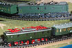
A pesar de llevar tiempo utilizando este tipo de decoder de sonido, no me había dado guerra la parte de control de motor, pero en este caso, con una máquina bastante antigua con motor de 2 poles, si que he tenido problemillas con ella.
Con un motor que aparentemente funciona correctamente en analógico, con una fuerza de tracción aceptable, una vez digitalizado y puesto en vía, el motor no tiene fuerza ni para arrancar ni mantenerse en circulación.
El motor de dos polos, está limpio de carbonillas y con las escobillas revisadas con contacto correcto. En analógico el funcionamiento es correcto.
En digital, lo valores que vienen por defecto en el decoder respecto a BEMF, funcionan bien en motores modernos, pero este motor, no se si por su construcción, por su antigüedad , por los dos polos, etc... a pesar de que en vació, con el tender sin tocar la vía, rueda, cuando toca la vía no tiene fuerza.
Estos son los valores por defecto del JMRI para este decoder y los valores después de muchas pruebas :


Son tan distintos los valores......además cada vez que los pruebas elegirías otros...
Están en modo básico, aceleración , frenada ,etc...
A pesar de lo que se explica sobre los distintos valores.....
Citar:
Track Voltage Reference
The Track Voltage Reference (CV64) is supposed to reflect the track voltage from the DCC system, which in turn is used by the chip to set the motor speed. But, it can be used to fool the chip into running at a different speed by pretending that the track voltage is different to reality. This can be useful as a substitute to altering the gearing of a motor; for example, setting the track reference voltage to 250 will make a typically "too fast" old Farish steam locomotive run with a more realistic slower top speed, and at the same time, also gains more control at the bottom of its speeds.
Adjust this value to give an acceptable range of speeds when using the entire throttle speed range, higher numbers will make the locomotive run slower.
Note that if you use a Sprog to program locomotives, and then move the locomotives to a layout with a different controller, chances are that the track voltage of the two systems are different; you might find settings need to be adjusted to cope with the real layout.
Motor Frequency
The Frequency used by the chip in controlling the motor can be changed using bit-7 in CV137 (thus CV137 takes values of 0 or 128 for this parameter). The default setting (0) means the motor is controlled at either 150Hz or 16Khz, the setting for the PWM Period (CV9, below) determines which is used.
For 2mm models, I'd be using at least 16kHz due to the values for PWM Period being higher than 134. With some motors (notably Faulhaber and Maxon), selecting the 32kHz option (CV137=128) may improve motor control. It may be necessary to experiment with this parameter, setting the other options and seeing what gives the best overall combination - the "alternative CV set" described at the bottom might be useful for this comparison.
Note that the other bits in CV137 control obscure features of the SL74/SL75 sound decoders, probably only relevant to very advanced setups. If using JMRI, the software takes care of things and keeps the bits "separate" on different tabs.
Motor PWM Period
The PWM period is set in CV9. This is setting how long the sensing period should be to measure the back-EMF.
For recent CT firmware and smaller motors, this takes values from 134 to 192 (values 1-63 are also valid, but would be applicable for motor designs not used in 2mm scale). I find values between 134 and 155 tend to work best. I set this by initially trying 134, then increasing the value and observing the results of the loco running at all speeds; I'm looking for smooth running and no stuttering. ("Recent CT Firmware" covers all the DCX74/75's I've ever seen).
P and I adjustment
The P and I values alter how the EMF sensed by the chip is used to alter the control of the motor. CV51 controls P, and CV52 controls I. Both take values from 0 to 255.
The setting of these depends in the specific motor and mechanical properties of the locomotive. I start by reading the values back from the chip, typically P=80 and I=40. Try halving both values (ie. P=40, I=20) and see if the effect is better or worse. Then pick another pair of values (keeping proportions similar), such as P=30, I=15, and slowly home in on the best values. Having got to the best pair of values, then try adjusting I on its own (bear in mind, any value from 0-255 is legal). This should, eventually(!), get smooth running in both directions at all speeds, particularly at low speeds with no lumpiness.
En este caso, tiene valores distintos para velocidades altas y bajas, y hay que ajustar en las dos situaciones.
- Reference voltage, Los valores de referencia de vía, entre 12 y 13 son los que mejor funcionan (130)
- Control Range, a 255 , valor máximo.
- Parameter K , un valor bajo ,9
- Parameter i, cualquiera muy alta , 179
- Parameter K slow, valor bajo , 10
- Parameter I slow, valor muy alto, 177
- Sampling Period, como viene por defecto , 8
Con estos valores , por lo menos está funcionando en vía y puede arrastrarse a si misma, pero ni mucho menos es un funcionamiento correcto.